| Working Atmosphere of the Hydraulic Press | |||||
| Temperature: 0℃—40℃ | |||||
| Humidity:Below 55%-85% | |||||
| Voltage:380V(-15%、+15%)/3P/50Hz | |||||
| Installation site:Clean,Little Dust | |||||
| Elevation:Below 1000M | |||||
| Machine noise measurement standard | |||||
| A-weighted sound pressure level :LPA≤82 dB(A) | |||||
| A weighted sound power level :LWA≤94 dB(A) | |||||
| Machine execution standard | |||||
| 1. JB3831-1999-Technical conditions of hydraulic machine | |||||
| 2. JB3915-85-Safe technical requirements for hydraulic machine | |||||
| Parameter | |||||
| Nominal Force | 2000KN | ||||
| Ejecting force | 400KN | ||||
| The Max. working pressure of the fluid | 25MPA | ||||
| Max. Open Height | 1100MM | ||||
| Max. Slide block stroke | 700MM | ||||
| On top of the piston stroke | 250MM | ||||
| Working table Dimension | Left-Right | 1000MM | |||
| Front-Back | 900MM | ||||
| Ram Speed | Empty | 100MM/S | |||
| Working | 6-8MM/S | ||||
| Return | 52MM/S | ||||
| Motor Power | 15KW | ||||
| Main Character of Hydraulic Press | |||||
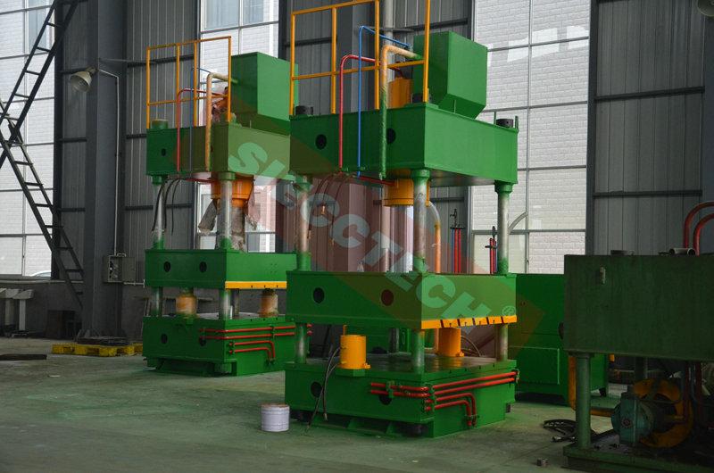
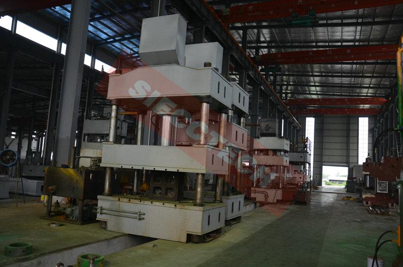
The machine's main engine has combined fully advantage in all oversea and domestic machines of the same catalog.The full machine is under finite element optimization design and industrial design and has reached the result in good overall performance and practical,durable,high rigidity and high reliability.At the same time,we have optimized the machine structure and popular design. The machine has independent actuating unit,electrical system,The relay control is applied,can be adjusted and semi automatic mode of operation.The working pressured, Slide block stroke range are adjustable according to the produce requirement.Two function Constant pressure and constant-distance forming can be reached.After constant pressure and forming,thre will be automatic return action With pressure and time delay. |
|||||
| Main Sturcture | |||||
| The machine is composed by two parts:Main Machine and Control Structure,and connected by pipeline and elecric device.The main machine has composition of machine body,main cylinder and stroke limit device.Control Structure include hydraulic power unit(dynamical system) and electronical cabinet.The main division and functin is discripped as below: | |||||
| 1.Machine Body | |||||
| The machine body is composed by foundation,top rail,slider block,working table,lower cylinder,upright column,locknut and adjusting nut.The precision is adjusted by adjusting nut and the locknut fixed on the top rail.Foundation,top rail,slider block are made in steel wileded structure.The plate's material is Q235-A steel,wilding adopt CO2 protective welding,heat-treatment will be in procedure after welding to eliminate internal stress. The outside of the machine main structure will be in good smooth,no obvious unevenness phenomenon ,welding seam formation ,welding slag and shed scar imagination.Compressor structure adopt optimization design by computer,It has good strength and stiffness. |
|||||
| 2.Main Cylinder | |||||
| The main cylinder is fixed to the top rail area by cylinder port shoulder and the big locknut.Lower end of the piston is connected by coupling flange,bolt and slider.The material of piston head is iron casting to act as guidance.The piston head has the imported YX type sealing ring in the opposite direction.The piston rod is provided with the O type sealing washer to divided the cylinder into to two cylinder with guidance sleeve,The guide sleeve excircle is provided O type sealing washer with the help of the flange and bolt locking to guarantee no any leakage and highly sel in cylinder.Cylinder flange is provided with a dust ring to ensure that the piston rod of the dust。 | |||||
| 3.Slider | |||||
| The movement of the slider is achieved by four vertical column guidance.The guide sleeve between slider and vertical column is alloy material with good abrasion resistance and easy replacement measures after abrasion.The below platform has equipped with T type slot to make the mold stable ,the detailed dimension can be provided under the requirement. | |||||
| 4.Lifting cylinder | |||||
| Lifting cylinder is a piston type cylinder equipped in the middle hold of the foundation to work for the top or drawing process. | |||||
| 5.Upright Column and lockout | |||||
| The material of upright column is 45# forged steel,and has process in drawing temper,the quenching hardness of the upright colume surface can reach HRC42-50.The material of Locknut is 45# forged steel,and has produced in blue handle,the connection between the upright colume and locknut is screw thread connection. | |||||
| 6.Stroke limit device | |||||
| The stroke limit device is equipped in the left side of the machine to control the stroke distance for the slider.It is composed by parallels,angle iron,induction block and contactless switch.Two parallels iron is fixed in the worktalbe and top rail to fix angle iron,there are guide groove in the angle iron ajust the travel switch and the stroke of the slider will be controlled. | |||||
| 7.Hydraulic pressure station | |||||
| The hydraulic pump is composed by fuel tank,axial plunger pump,motor,two way cartridge valve,oil filter and air cleaner. | |||||
| (1)The tanker is welded by Q235 Steel,the front end is equipped with a pressure gauge for a easy obersation of the pressure and pressure-adjustment.In the lower part of the bracket is equipped with a pressure gauge level gauge, to observe the level.Open the upper cover ,for fuel filling.In the fuel tank is provided with a cleaning mouth, open cover capable of cleaning the tank. | |||||
| (2)Fuel tank for the steel plate welded structure, by shot peening and rust prevention treatment,there are clean mouth in the side of tank and oil level ruler.The air clear,valve integrated blocks are in ordered arrangement in the top of tanker cover. | |||||
| (3)The main hydraulic piping with flange connection, with reasonable layout of the seismic pipe clamp to prevent pressure pipeline vibration and leakage.Before the pipeline installation,there will be process of pickling and passivation treatment to guarantee oil cleanliness. | |||||
| (4)Axial plunger pump The hydraulic system use YCY14-1B axial plunger pump,the main specification and instruction is included in the axial plunger pump manual. |
|||||
| (5)Two way Cartridge Valve | |||||
| The structure include Inserting piece,control panel,piot control valve and Integrated valve block. | |||||
| A.Inserting pieces is composed by valve pieces,spring,seal,valve pocket.It can be cone valve or slide valve structure.Main fuction is to control oil flow direction,pressure and flow rates n the oil pipe. | |||||
| B.Control panel is composed by embedded various pilot control and other components in the cover panel.The main function is to fix inserting pieces.The Pilot control and other components will integrated with other pilot valve to control the inserting pieces working status.The control panel is divided into directional control cover plate,pressure control,flow control cover plate. | |||||
| C.pilot control valvei is fixed in the control cover to control the movement of the plug of small diameterelectromagnetic reversing valve.The element is standard directional control valve. | |||||
| D.integrated valve is to used to install the plugin,control and other control valve cover. | |||||
| Hydraulic System | |||||
| Hydraulic System is composed by energy conversion device(Pump and hydro-cylinder) and energy delivery device(Tanker and pipeline).By means of electrical control system,drive slide block to complete a variety of operation cycle.The hydraulic system uses large flow cartridge valve.In the pump inlet equipped with oil fume filter to prevent impurities from entering the hydraulic system and guarantee the normal working of the oil-way.System equipped with oil-level display and oil-temperature display and also air filter.Tanker is steel welded,tanker side has cleaning window,bottom equipped with plug screw forOil drain and sewer. To prevent the slider out of control and be down,the machine equipped with Hydraulic support safety circuit.In a piston master cylinder cavity adopts hydraulic support safety circuit to make sure the sercurity. This machine has the adjustment, semi-automatic mode choose. |
|||||
| 8.Electrical control system | |||||
| (1)The machine has independent electrical control cabinet and moveable button station. The electrical control cabinet is used to equip Power control unit,for example,The control of total power and motor starting control element and also Protection switch and a leakage protector.There are Ventilation facilities within the cabinet and with a good seal to provent the ingress of the dust.The installation location of the cabinet should be instructed by the buyer(The producer or the supplier will notify in advance) Operation station has operation button and function switch button for action of every part,the motor start and stop button and alarm and monitoring indicator to grasp the working state of the machine. Moveable button station has the button for two-hand press,return,emergency stop,back. |
|||||
| (2)the machine standard power is AC380V/50HA,control electronic power is AC220V,Pilot valve magnet power supply for DC24V. | |||||
| 9.Operation System | |||||
| (1)Adjustment(inching):Operate related function button to achieve this action,every press of the button will arrive one inching,mostly for the machine adjustment and mold replacement. | |||||
| (2)Hand Movement:press related button ,When the press motionless button or to the action of static limit when motion ceases. | |||||
| (3)Semi-automatic:Move operation sation use two hands,when press two buttons,finish one procedure. | |||||
| (4)Semi-automatic action has three type: | |||||
| Normally no push-out process | |||||
| Fast down of the slider→slow down of the slider press→Slide pressure delay and decompression →Slider back | |||||
| Fast down of the slider→slow down of the slider press→slider pressure delay and decompression→slider back-Manual lifting →Manual return | |||||
| Drawing process | |||||
| Fast down of the slider→slow down of the slider press→slider pressure delay and decompression→slider back | |||||
| (5)Slider stroke is controlled by stroke button | |||||
| (6)Master cylinder pressure by time relay setting | |||||


